The Importance of Pull Direction in Cable Installation and the Role of Bends
Several factors affect cable pulling tension. These impact the feasibility of the cable installation. One overlooked factor is the effect of pull direction. With the right tools and planning approach, stresses placed on cable during a pull can be estimated accurately. Measures can then be taken to avoid damaging this asset.
Factors Affecting Cable Tension
Before installing cable in conduit, many factors must be considered in the planning process to avoid approaches that might damage the cable or render the pull impossible. The type of cable and its jacket material and weight; the conduit material and its placement technique; the type of hauling rope or cable; the position and type of reel stand; the conduit proving equipment; the winch model and force capacity; and the lubricant choice and application method all affect the feasibility of a cable installation. But when it comes time to pull, how does one manage all these data points to ensure a safe and efficient cable installation? Planning is always the best answer.
Site Topography and Cable Routing
The topography of the site and preexisting infrastructure affect the route the conduit and cable will take. Design engineers must develop a route that avoids underground and above-ground obstacles, but which allows the cable to be installed without exceeding the tension and sidewall pressure limits set by the cable manufacturer. Engineers have some flexibility in defining the cable route, but the realities of the site determine the rest.
Bends and other displacements have a significant impact on the forces exerted on a cable as it is drawn through the conduit. Intuitively we know that, with gravity assist, pulling a cable down a slope is generally easier than hauling it upgrade, so some may assume that starting the pull at the higher end of the conduit always requires the least amount of winch force. However, the position and magnitude of the bends placed in the overall conduit design must be analyzed to determine the optimal pull direction. The force required to traverse these bends may actually be minimized when starting at the lower end of the conduit and pulling uphill. To understand the effects of bends in pulling tension and sidewall pressure analyses, one must have a basic understanding of the mathematical equations used to assess these forces.
| Related Content: Measuring Friction on Polywater’s Friction Table |
Understanding Tension Equations
In pulling tension equations, the coefficient of friction, which is a dimensionless constant (µ), determines the amount of friction generated on the cable during its installation in duct. It acts as a multiplier to the weight and adds tension for straight and sloped conduit sections. In bends, the coefficient of friction is part of the multiplier to the tension through the “cosh.” It sits in the exponent of the natural log (e) in that form of the equation.
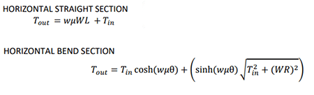
This means that bends exponentially increase the tension exerted on cable as it migrates through these displacements. If the bends are not symmetrical in the conduit layout, it is preferrable to first pull through the bends to minimize the amount of tension entering them.
Simplifying Analysis with Pull-Planner
Performing tension calculations by hand or even in a spreadsheet can prove daunting, but a free tool exists to help make the analysis easier for engineers designing the system and for the workers installing it: Polywater Pull-Planner™. The Pull-Planner cable tension estimation software uses industry-established force equations to automatically work the difficult math for the designer. But it does more than that; once the cable and route data are entered into the software, the program calculates tension and sidewall pressure for each segment of the cable haul to provide a view of what is happening to the cable in each section of the installation. Furthermore, the program allows for “what if” scenarios. The user can reverse the direction of the pull with one mouse click to immediately display the tension and sidewall pressure analysis in the opposite direction.
Real-World Examples
Let’s go through two examples to demonstrate …
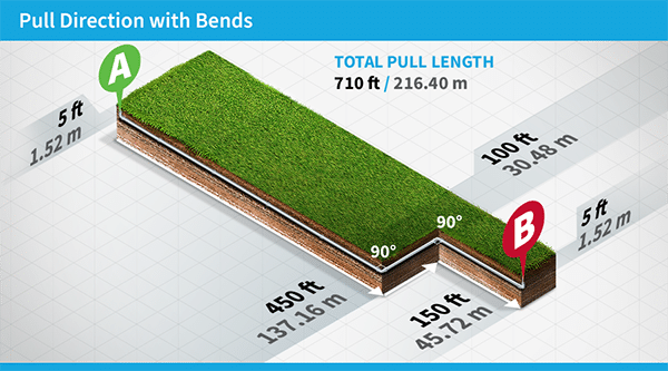
This graphic shows the layout of a typical electrical cable haul between utility poles. Note that there is a 5’ (1.5 m) vertical segment at either end of the conduit run and a cluster of bends near Point B. Both vertical components are equal in length and orientation and will therefore nullify each other in tension equations. If no obstacles are present at either end of the conduit for the placement of the cable reel, the installer theoretically can choose the point at which to start the pull. However, if haul direction is not verified against the cable’s maximum allowable tension and sidewall pressure or against the winch’s capacity rating, the stress placed on both will be much higher in one direction than the other. Let’s see what the Pull-Planner calculates as the final tension for each pull direction.
| Related Content: Coefficient of Friction in Cable Pulling — Part 1 |
Pulling from A to B
In the above example, we have mapped the cable’s path through each segment of the conduit layout – from Point A to Point B. The program calculates the final tension on the cable at 4,088 lbs (8.38 kN) with maximum sidewall pressure of 1,940 lbs/ft (13.26 kN/m).
Pulling from B to A
When the pull direction is reversed in the software, the Pull-Planner shows that a lower final tension is achievable. Here, the final tension exerted on the cable in Segment 5 is 3,225 lbs (6.62 kN) with maximum sidewall pressure of 1,522 lbs/ft (10.42 kN/m) – an approximate 21% reduction in tension and sidewall pressure.
These examples illustrate the significant impact of bends on overall hauling tension. But what happens when there are elevation changes between the starting and ending point of a cable pull? Does the impact of a slope (or gravity) nullify the influence of bends in a cable haul? Let’s review another example.
| Video: Polywater Pull-Planner Cable Installation Planning Software |
Pull Direction with an Elevation Change and Bends
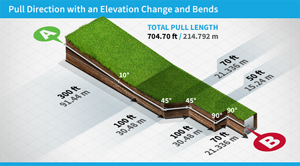
In the graphic above, we see that one end of the conduit is located at the top of a 10° grade (Point A) and there are several bends clustered at the lower end of the conduit run (Point B). It may be tempting to place the reel at Point A and the winch at Point B to start the pull downhill. However, the first two bends are significant (90°) and are followed by two more 45° bends before the winch must work against gravity. Tension should be verified from both directions to determine the best pull direction.
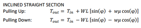
We remember from the Horizontal Straight Section and Horizontal Bend Section equations provided earlier that the coefficient of friction acts to exponentially increase tensions entering bends. What do the equations look like for straight sloped sections? The coefficient of friction is still a multiplier but is affected by the angle of slope and the gravitational direction of the cable haul.
Below, you see the pull mapped in the Pull-Planner software where all the straight sections and bends are clearly defined – straight section lengths and slopes – and bend types, angles, radii, and lengths. The pull direction is from Point A to Point B.
Sloped Pull – Point A to Point B
The calculated ending tension is 8,249 lbs (36.81 kN).
Now, what happens to the tension values if the haul is reversed so that the cable is pulled through the bends first? Tensions drop significantly.
Optimizing the Cable Pull Direction
Note that the ending tension when hauling uphill from B to A has been reduced to 4,834 lbs (21.58 kN), nearly half the tension of the originally calculated pull direction. This analysis reveals that, in this scenario, initiating the pull through the bends first leads to a significant and, perhaps, unobvious reduction in the overall tension.
| Related Content: Data from Polywater® Helps Predict Coefficient of Friction in a Cable Pull |
Enhancing Efficiency with Tension Insights
The Pull-Planner simplifies the analysis and site planning process for engineers. It allows them to assess the optimal pull direction based on the estimated tension and offers an invaluable benefit to the installation crews. Understanding the required reel placement and the initial tension of the haul enables installers to choose a winch and reel stand that are fit for purpose. Moreover, if manual labor is necessary to turn the reel due to the absence of a motorized option, the project manager can proactively plan for an adequate number of workers on-site, ensuring a seamless and efficient execution of the installation plan. This foresight not only enhances the planning process but also minimizes delays while optimizing labor on the job site.
Confidence in Cable Installation
The best pull direction for any cable installation is not always a straightforward determination. Obstacles at either end of the conduit layout may dictate the direction of the haul and the equipment required for the job. Installations should be analyzed in both directions to ensure that bends or slopes do not increase pulling tension beyond the established limits of the cable or winch. With the use of the Polywater Pull-Planner planning tool, engineers and contractors have confidence that all job materials and installation techniques are assessed and verified to optimize the cable installation, including optimal pull direction.