How to Avoid Crushing Fiber Cable During Installation
Maintaining minimum bend diameter (MBD) is key to good fiber installation practice. Minimum bend diameter (sometimes called out as minimum bend radius) is not maintained when fiber cable is installed over small rollers. In fact, the use of channel rollers and corner guides is not allowed. According to experts, the most common cause of cable damage is the use of small diameter rollers. Incorporating quad blocks into the installation design is an important way to maintain the MBD.
This paper describes the research and physics of fiber crushing. It further explores the impact of incorporating quad blocks into the installation design. Since a quad block is a fixed surface, the question is “How much tension is added to a pull?”
How fiber gets crushed.
Research data on crushing forces and bend diameter limitations were published in a 2011 paper presented by Corning Cable to the International Wire and Cable Symposium (IWCS). In this study, a special apparatus was designed and used to test fiber cable in various combinations of load, bend radius, and contact angle. Multiple types of fiber cable from different manufacturers were tested, and all showed signs of damage when pulled with too much tension or around a bend with too small a radius. This is what cable manufacturers call “Outside the Box”. Chart 1 shows the relationship between installation load and bend diameter.
Graph 1: “The Box” shows the relationship between Pull Tension and Bend Diameter.
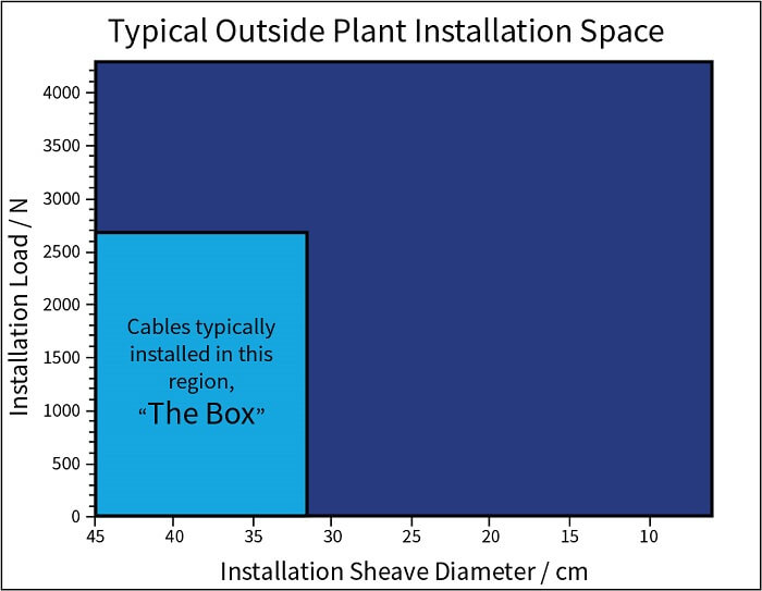
This shows that when installation loads are too high or when the sheave diameter is too low, fiber cable may be damaged. “Outside the Box”, the sidewall tension is too high and has become a crushing force.
The IWCS study further confirmed that even a slight (shallow) contact angle has the possibility of damaging fiber. “A contact angle as slight as 10 degrees does just as much damage as one of 90 degrees.” A 10-degree bend is shallow, almost imperceptible. See Diagram 1 below.
Diagram 1
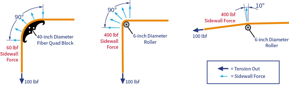
The bend diameter has direct influence on sidewall (crushing) force. The contact angle does not.
In other words, pulling across wheels, rollers, or standard quad blocks will cause damage even if it appears the cable is being pulled straight. Even moving the cable across a manhole or pedestal edge can cause damage, as these edges act as small contact bends. Thus, the severity of contact angle is not an important factor; rather the radius of the bend is all-important.
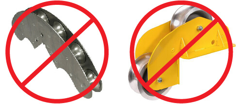
In a standard quad block, shown here, each small roller contributes a sidewall (or crushing) force to the fiber cable.
What Is the Crushing Force? How Is It Determined?
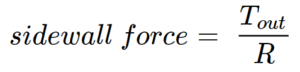
Crushing force is the relationship between the pulling force and the radius of the bend. When a cable is pulled into a bend, the sidewall (crush) force is inversely proportional to the length of the bend radius. As the radius gets smaller, the sidewall force increases. Sidewall/Crushing force is determined by the following equation:
Industry standards clearly define the maximum pulling force for fiber optic cables. For most outside plant fiber, installation load is limited to below 600 lbf (2700 N). Cable manufacturers also restrict bend radius depending on the cable diameter. By managing the bend radius, it is possible to avoid sidewall forces that crush and damage the fiber. A typical lip roller designed for power cable has a diameter of 5 inches (13 cm). This is four times smaller than the MBD suggested for a 72-count fiber cable.
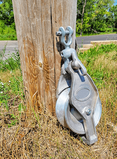
This popular stringing block is called out as a 7-inch (18 cm) OD, but the hub diameter is only 5 inches (13 cm).
Minimum crush strength for fiber cable is described in Telcordia GR 20 CORE2 as 1,500 lbs./ft (21.9 kN/m). Recommended guidance for maximum sidewall tension is 50% of that value. The IWCS study proved that fiber can be damaged with loads as low as 200 lbf (0.9 kN) pulled around a 6-inch (15 cm) wheel. The sidewall force in this scenario is 800 lbf/ft (12 kN/m). This agrees well with current sidewall guidance.
| Related Content: Measuring Cable Pulling Friction with a Reel Test |
Sidewall force is amplified around tight-radius bends. This is the force that damages fiber. Managing this sidewall force becomes even more critical with higher fiber counts.
What are Fiber Quad Blocks?
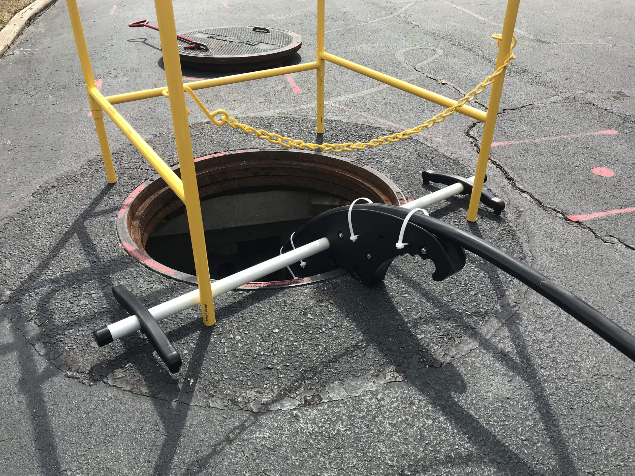
Fiber Quadrant Blocks are one of the many devices used in cable placement and are necessary to ensure that fiber optic cabling is protected during installation, especially when placing newer high-count fiber cables. Quadrant blocks are used to protect fiber optic cable during installation by creating a ‘path’ that allows the cable to make a gradual 90° turn for easy pulling through manhole openings, ducts, etc.

A typical standard quadrant block is comprised of a series of rollers on a frame that serves as a guide to ensure that fiber optic cable is pulled along a proper bend radius to prevent breakage of the glass fibers that make up the core of the cable. Up until now, a standard quadrant block has been used to feed the cable into/out of areas such as manholes and handholes through underground ducts and aerially onto utility poles. In theory the cable should travel along the rollers, and the rollers act as a guide to ensure that the cable is never bent below its minimum bending radius.
However, this has proven not to be a reliable method of preventing breakage. The rollers themselves have proven to be a problem as they apply too much contact pressure to the cable, causing breakage to occur when the cable bends from roller to roller. The cable has a slight deflection over each roller thus the bend radius of concern comes from each small roller rather than the full block. And, each small roller is typically below the minimum bend diameter. In the past, this issue was temporarily solved by modifying the quadrant blocks with split pipes and steel forms for a more constant path of travel for the cable.
After extensive research and testing, fiber quad blocks were designed and developed as a whole new take on quadrant blocks: a solid bodied quadrant block specifically for use when placing fiber optic cables. Using a new, gently curving, solid design installers were able to provide a smooth contour, maintain the required bend radius of the fiber optic cable and eliminate cable breakage caused by contact and sidewall pressure, unlike with traditional rollers.
Preferred quadrant block has a large radius with smooth diameter channel.
Measuring Cable Tension and Sidewall Forces in a Fiber Quad Block.
A fiber quad block essentially creates a smooth, large-radius channel to direct the fiber optic cable during installation. This means that the cable moves along the surface with some degree of friction, resulting in a nominal tension increase.
| Related Content: Coefficient of Friction in Cable Pulling — Part 1 |
To determine the coefficient of friction, two different fiber quad blocks were mounted to a test device. A back tension was added to a fiber optic cable as it was pulled across the surface using a constant-speed winch. Tension force was measured using a load cell. This force was used to back calculate coefficient of friction values for the fiber quad block surface. In this case, Polywater’s Pull-Planner™ was used to iteratively derive the COF (µ).
The smooth plastics typically used in these installation devices have low friction and work well with fiber optic cable. High-performance cable lubricants further lower COF, even across low-friction surfaces. Results follow below.
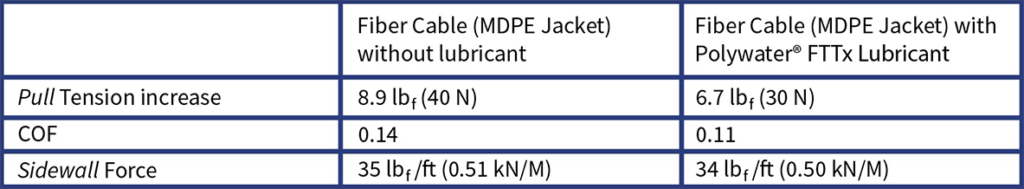
Fiber Quadrant Block A
Diameter = 40 inches (100 cm)
Arc Length = 24 inches (60 cm)
Tin = 50 lbf (222 N)
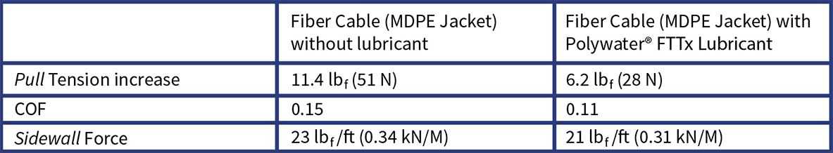
Fiber Quadrant Block B
Diameter = 64 inches (162 cm)
Arc Length = 46 inches (117 cm)
Tin = 50 lbf (222 N)
The fiber quad blocks add a short section of arc to the cable pull with minimal tension addition. The use of fiber quad block ensures that the sidewall tension or crushing force remains low. For the same 50-lbf (222 N) incoming tension, a 7-inch (18 cm) roller in the above scenario creates a sidewall tension of 171 lbf/ft (2.5 kN/m). This is getting close to the force that will start to damage the cable.
| Related Content: Planning cabling projects improves success and safety |
The measured COF for the fiber quad block channel material is even lower as the sidewall force increases, ranging from 0.08 unlubricated down to 0.05 lubricated using Polywater’s friction table method. This further supports the use of fiber quad blocks instead of the rollers and standard quad blocks commonly used in past installations.
Pulling It All Together
Installers should be aware of these best practice recommendations. For high-count or longer fiber installations, use of quad blocks is recommended. This improves the odds of a safe installation without damage to the fiber cable.
Have any questions?
References
1 Quinn, C, Seddon D. 2011. Installation of Fiber Optic Cable Outside the Box. IWCS.
2 Telcordia Technologies. 2013. GR 20 CORE, Generic Requirements for Optical Fiber and Optical Fiber Cable