Addressing the Rise of the “Zero-Splice” Rule in Cable Undergrounding
Learn why zero-splice cable installation is the preferred method of installation and how new technologies and materials make it more achievable.
Cable splicing as part of an underground cable project, while necessary in some installations, is not ideal for the overall reliability of an underground system. Historically, spliced cables have a higher probability of inferior performance and failure. This prompted a need to reduce splices in system design driven by several factors. First, manual splicing techniques involve complicated processes that are labor and time intensive, leading to potential errors in workmanship. Second, splices need to be placed inside enclosures, which introduces additional construction resources and produces spoils that must be managed. Lastly, the aforementioned factors create additional project costs. When considering all these aspects, the less splices in the design the better.
Recently there has been an increase in new cable installation projects calling for “zero splices.” This comes from network owners and planners within industries where sensitive, mission-critical electronics are involved, places such as data centers.
So how is cable installed and connected without using splices?
The goal has always been to have as few splices as necessary to complete a cable installation. If one could eliminate all splices, essentially, they would be removing a vulnerability in the system.
The “zero splice” requirement seems like a tall order to deliver; however, it is attainable. It is happening now in underground cable-in-conduit installations, and several key tactics make it possible. These include understanding the materials science of conduits and cables to achieve longer cable pulls and the use of key component technology to connect the system. In this article, we will shed light on this trend and how installers, with the help of manufacturers, are realizing this seemingly out-of-reach goal for their underground electrical network owners.
Revisiting the Cable Pull Plan
Minimizing the need for splices in a cable installation starts at the planning stage by examining the installation site. The topographical and structural characteristics of the site play an important role in determining the planned route of the conduit and cable installation. Each site has unique requirements, and these can dictate the direction in which a cable is installed. They also can affect the distance a cable can be pulled. Considerations such as the slope or angle of the cable pull direction, the number of bends, and the presence of any significant bends in the conduit line also determine if a “zero splice” installation is possible.
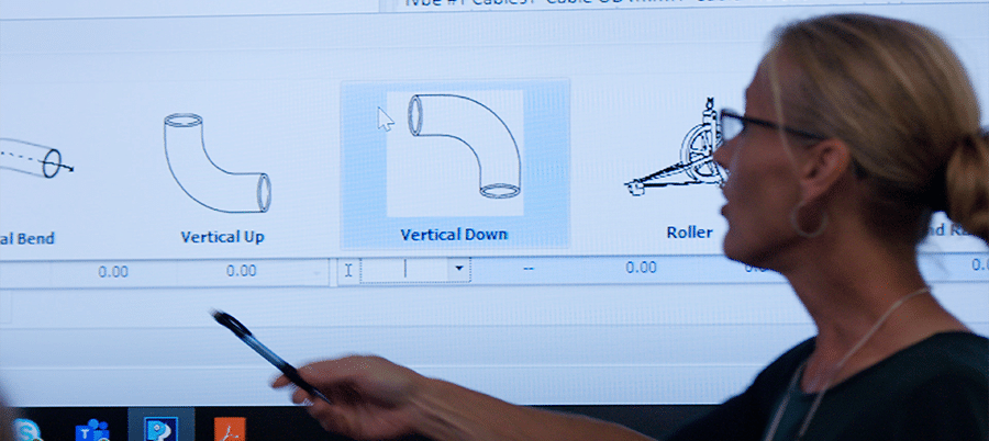
The use of cable pull-planning software, like the Polywater® Pull-Planner™, early in the planning stages of a network design allows engineers and contractors to closely estimate cable tension and coefficient of friction (COF) in the cable pull. The software allows planners to incorporate different types of high-performance cable lubricants, which facilitates the possibility of safer long-distance cable pulls by reducing COF. It also gives them the ability to review the relationship between cable and conduit diameters and verify the probability of jamming that could occur during the pull. Additionally, engineers and contractors can simulate a reversal of the cable pull direction to see if there are any advantages. These verifications not only identify any potential reduction in cable tension and COF but can lead to the possibility of a longer distance cable pull — which can eliminate the need for a cable splice.
Understanding the Materials Science
Another key factor in achieving zero cable splices is understanding the unique material properties of the cable jacket and conduit material types that are specified for the installation. Common materials are PVC, HDPE, LLDPE, and fiberglass. Each of the materials has distinctive properties and surfaces qualities. In some cases, there are multiple conduit materials used within the same project. This is important to note this when planning the pull.
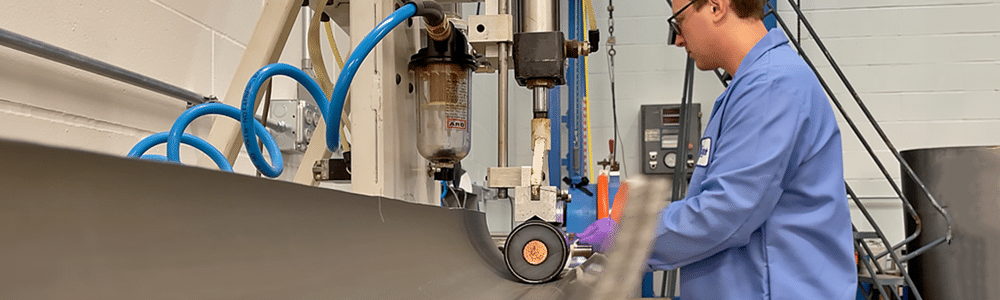
As the cable is pulled through the conduit, friction created between the surfaces of the cable jacket and conduit can yield a different COF based on the combination of materials. Take for example fiberglass pipe or conduit. It is used because of its durable qualities and ability to withstand a wider temperature range than PVC. However, it has been shown to display higher COF values than the plastics previously mentioned. The lower the COF the safer it is for both cable and conduit. However, when a high-performance cable lubricant is introduced, it drastically lowers COF and enables the cable to be pulled more safely across greater distances.
Understanding the COF between cable and conduit materials coupled with how the use of the right high-performance cable lubricant can significantly reduce it gives planners the data they need to design longer continuous pull lengths without the need to splice.
| Related Content: Science of Cable Lubrication: Film thickness and quantity recommendations |
Addressing the Cable Termination Points
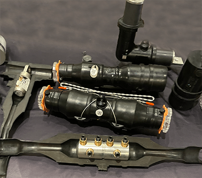
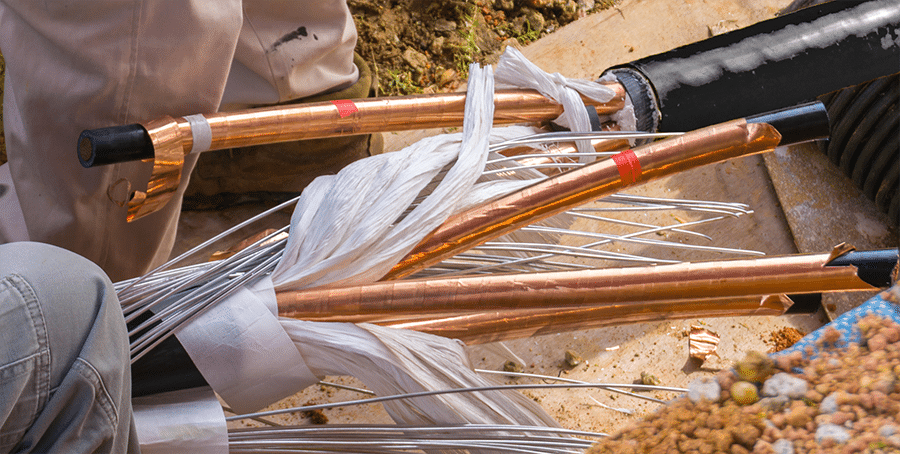
Today, with the help of cable, conduit and lubricant manufacturers, installers can pull cable greater lengths than ever before. Yet, the cable eventually terminates and needs to be connected. To achieve this without needing splices, contractors opt for the use of dead breaks on the cable to connect from a transformer or switch gear to a junction bar in a sectionalizing cabinet. This provides a cleaner and more accessible solution for maintenance during a system fault or for a potential replacement in the unlikely event of a cable failure. It also provides a safer operating environment for maintenance crews as the dead break is typically connected in an above-ground location like a sectionalizing cabinet. The use of dead breaks effectively connects the circuit while facilitating the creation of a system without splices.
Achieving Zero Splices
Reducing the number of splices, and even eliminating them where possible, should be a goal in planning any cable installation and is now more attainable than ever. With the right tools and materials, engineers and contractors can help network owners build a more reliable system ── one that protects their critical assets and enables all of us to realize the benefits of a dependable, always-on network.
Turn to the Experts at Polywater
If you have questions about how Polywater’s services or products can help achieve your zero splice goals, don’t hesitate to reach out. We look forward to collaborating with you.